- 您现在的位置:买卖IC网 > Sheet目录1228 > MAX8536EVKIT (Maxim Integrated Products)EVAL KIT FOR MAX8536
�� �
�
�MAX8536� Evaluation� Kit�
�Reverse� Current�
�The� IC� controller� detects� reverse� current� during� normal�
�operation� by� monitoring� the� voltage� difference� between�
�PS_OUT+� and� VBUS+� using� the� on-resistance�
�(R� DS(ON)� )� of� both� N-channel� MOSFETs,� N1� and� N2.� N1�
�and� N2� have� a� combined� on-resistance� of� 7m� Ω� (typ).�
�The� IC� controller� detects� a� reverse-current� fault� condi-�
�tion� when� VBUS+� voltage� minus� PS_OUT+� voltage� is�
�greater� than� 0.03V� (typ),� after� a� 500ms� blanking� period�
�when� the� gate� drive� first� turns� on.� The� EV� kit� detects� a�
�reverse-current� fault� condition� if� 4.3A� (typ)� (4.3A� x� 7m� Ω�
�>� 0.03V)� are� sourced� from� V� BUS+� to� PS_OUT+.� During�
�a� reverse-current� condition,� the� IC� controller� turns� off�
�the� MOSFETs,� asserts� a� logic� low� on� the� FAULT� output,�
�and� latches� off.�
�F� A� U� L� T� Conditions�
�The� FAULT� PCB� pad� is� connected� to� the� IC’s� FAULT�
�pin.� The� FAULT� pin� is� pulled� to� VBUS+� by� R2� during�
�normal� operation.� During� an� overvoltage,� undervoltage,�
�or� reverse-current� fault� condition,� the� IC� enters� the� fault-�
�condition� state� where� the� FAULT� pin� is� pulled� low� and�
�the� GATE� pin� is� discharged� to� ground.� This� turns� off�
�both� MOSFETs.� The� fault� condition� does� not� latch� dur-�
�ing� an� undervoltage� condition.� The� IC� latches� off� during�
�a� reverse-current� or� overvoltage� fault� condition.� Cycle�
�the� input� power� supply� or� enter� shutdown� mode� using�
�JU1� to� clear� the� latch� (see� Table� 2� for� the� fault� states’�
�descriptions).�
�Capacitors� C4� and� C5�
�Install� ceramic� capacitors� on� C4� and� C5� to� filter� input�
�and� output� bus� noise.� Select� a� ceramic� capacitor� with� a�
�value� between� 1μF� and� 4.7μF� in� a� 0805� case� size� with�
�a� voltage� rating� of� 6.3V� (min).�
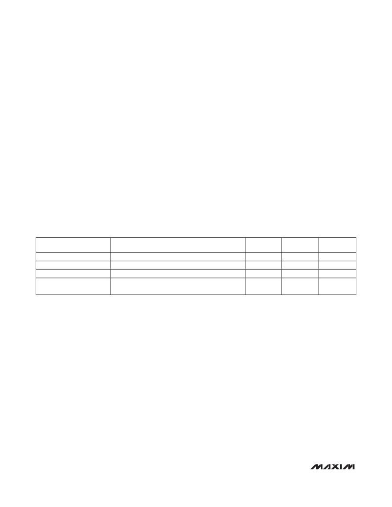
�Table� 2.� MAX8356� Fault� States�
�FAULT� STATE�
�Undervoltage� Lockout�
�Undervoltage� Protection�
�Overvoltage� Protection�
�Reverse-Current� Protection�
�CONDITIONS�
�PS_OUT+� <� 2.7V� (typ)�
�PS_OUT+� <� 2.9V�
�VBUS+� >� 5.75V� and� PS_OUT+� >� (VBUS+)� +� 0.01V�
�PS_OUT+� <� (VBUS+)� -� 0.03V� and� MOSFETs� ON� for�
�t� >� 0.5s�
�MOSFETs�
�Off�
�Off�
�Off�
�Off�
�FAULT�
�OUTPUT�
�VBUS+�
�Low�
�Low�
�Low�
�LATCHING�
�No�
�No�
�Yes�
�Yes�
�4�
�_______________________________________________________________________________________�
�发布紧急采购,3分钟左右您将得到回复。
相关PDF资料
MAX8555AEVKIT
EVAL KIT FOR MAX8555
MAX8814EVKIT+
KIT EVAL FOR MAX8814
MAX8821EVKIT+
KIT EVAL FOR MAX8821
MAX9235EVKIT+
KIT EVAL FOR MAX9235
MAX9258EVKIT+
EVAL KIT FOR MAX9258
MAX9390EVKIT+
KIT EVAL FOR MAX9390
MAX9392EVKIT+
KIT EVAL FOR MAX9392
MAX9507EVKIT+
KIT EVAL FOR MAX9508
相关代理商/技术参数
MAX8537EEI
功能描述:DC/DC 开关控制器 RoHS:否 制造商:Texas Instruments 输入电压:6 V to 100 V 开关频率: 输出电压:1.215 V to 80 V 输出电流:3.5 A 输出端数量:1 最大工作温度:+ 125 C 安装风格: 封装 / 箱体:CPAK
MAX8537EEI+
功能描述:DC/DC 开关控制器 Dual-Synchronous Buck Controller RoHS:否 制造商:Texas Instruments 输入电压:6 V to 100 V 开关频率: 输出电压:1.215 V to 80 V 输出电流:3.5 A 输出端数量:1 最大工作温度:+ 125 C 安装风格: 封装 / 箱体:CPAK
MAX8537EEI+T
功能描述:DC/DC 开关控制器 Dual-Synchronous Buck Controller RoHS:否 制造商:Texas Instruments 输入电压:6 V to 100 V 开关频率: 输出电压:1.215 V to 80 V 输出电流:3.5 A 输出端数量:1 最大工作温度:+ 125 C 安装风格: 封装 / 箱体:CPAK
MAX8537EEI-T
功能描述:DC/DC 开关控制器 RoHS:否 制造商:Texas Instruments 输入电压:6 V to 100 V 开关频率: 输出电压:1.215 V to 80 V 输出电流:3.5 A 输出端数量:1 最大工作温度:+ 125 C 安装风格: 封装 / 箱体:CPAK
MAX8537EVKIT
功能描述:DC/DC 开关控制器 RoHS:否 制造商:Texas Instruments 输入电压:6 V to 100 V 开关频率: 输出电压:1.215 V to 80 V 输出电流:3.5 A 输出端数量:1 最大工作温度:+ 125 C 安装风格: 封装 / 箱体:CPAK
MAX8538EEI
功能描述:DC/DC 开关控制器 RoHS:否 制造商:Texas Instruments 输入电压:6 V to 100 V 开关频率: 输出电压:1.215 V to 80 V 输出电流:3.5 A 输出端数量:1 最大工作温度:+ 125 C 安装风格: 封装 / 箱体:CPAK
MAX8538EEI+
功能描述:DC/DC 开关控制器 Dual-Synchronous Buck Controller RoHS:否 制造商:Texas Instruments 输入电压:6 V to 100 V 开关频率: 输出电压:1.215 V to 80 V 输出电流:3.5 A 输出端数量:1 最大工作温度:+ 125 C 安装风格: 封装 / 箱体:CPAK
MAX8538EEI+T
功能描述:DC/DC 开关控制器 Dual-Synchronous Buck Controller RoHS:否 制造商:Texas Instruments 输入电压:6 V to 100 V 开关频率: 输出电压:1.215 V to 80 V 输出电流:3.5 A 输出端数量:1 最大工作温度:+ 125 C 安装风格: 封装 / 箱体:CPAK